
Identify what each network component does, compare common enterprise designs, choose appropriate media, and isolate physical-layer faults.
Learning objectives
- Differentiate routers, Layer 2 switches, Layer 3 switches, firewalls, IPS devices, APs, controllers, endpoints, servers, and PoE.
- Compare two-tier, three-tier, spine-leaf, WAN, SOHO, on-premises, and cloud designs.
- Select copper, multimode fiber, or single-mode fiber for a stated requirement.
- Use interface counters to recognize speed, duplex, collision, and cabling problems.
Component roles
A Layer 2 switch forwards Ethernet frames inside a broadcast domain using a MAC address table. A Layer 3 switch adds hardware-based IP routing. A router connects IP networks and chooses paths using its routing table. A next-generation firewall enforces policy using addresses, applications, users, and inspection; an IPS looks for malicious traffic patterns. Access points bridge wireless clients to the wired network, while controllers centralize wireless policy and operations.
Enterprise architectures
A two-tier campus collapses distribution and core functions and suits many small or medium sites. A three-tier campus separates access, distribution, and core for scale and fault isolation. A spine-leaf fabric gives every leaf a predictable equal-cost path through each spine and is common in data centers. WANs connect geographically separated sites. SOHO networks combine several roles in a small device, while cloud and on-premises describe where compute and network services run.
Media selection
Copper Ethernet is inexpensive and can deliver PoE, but normal horizontal cabling is distance-limited and vulnerable to electromagnetic interference. Multimode fiber is common for shorter building and data-center links. Single-mode fiber supports much longer distances. Connector type, transceiver wavelength, fiber type, supported speed, and optical budget must all match.
Reading interface evidence
A down/down interface usually points to missing carrier, cabling, optics, or a far-end problem. Administratively down means the interface is shut in configuration. CRC and input errors suggest damaged media, interference, optics, or duplex problems. Late collisions strongly suggest a duplex mismatch on legacy half-duplex Ethernet. Rising output drops usually indicate congestion, not a bad cable.
Command reference
show interfaces status
show interfaces gigabitEthernet 0/1
show interfaces counters errors
show controllers ethernet-controller
show inventory
show power inline
show logging | include LINK|LINEPROTOPacket Tracer Lab 2 - Diagnose Four Interface Failures
Topology: PC-A -- SW1 == trunk == SW2 -- PC-B, with R1 attached to SW1
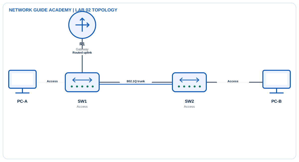
Addressing and design
- Management subnet: 10.10.10.0/24
- R1 G0/0: 10.10.10.1/24
- Switch management addresses: .11 and .12
Tasks
- Create a healthy baseline and record interface states and counters.
- Introduce one fault at a time: shutdown, wrong cable/port, forced speed mismatch, and forced duplex mismatch where the simulator supports it.
- For each fault, record the symptom, most useful command, root cause, and corrective action.
- Restore automatic speed/duplex or matching values and verify that error counters stop increasing.
Detailed configuration workflow
- Record the normal interface state and counters before inserting faults.
- Test four faults separately: shutdown, wrong cable/link, speed or duplex mismatch, and trunk inconsistency.
- After each repair, clear or note counters and confirm they remain stable during traffic.
Example configuration and commands
show interfaces status
show interfaces gigabitEthernet 0/1
show interfaces counters errors
show controllers ethernet-controller
show inventory
show power inline
show logging | include LINK|LINEPROTO
Verification
- show interfaces status
- show interfaces counters errors
- show logging
- ping 10.10.10.1
Expected healthy evidence
- show interfaces status: connected ports show connected and the intended VLAN or trunk role.
- show interfaces counters errors: CRC, collision, and input-error counters remain stable in a healthy lab.
- show logging: link transitions correspond to the test timestamps and no continuing flaps remain.
Troubleshooting matrix
| Symptom | Inspect | Likely correction |
|---|---|---|
| administratively down/down | show interface status and running config | no shutdown |
| down/down | Inspect both ends, cable type, optics, and remote power | Restore physical carrier |
| up/down or rising errors | show interfaces and compare speed/duplex | Use compatible settings, preferably auto/auto |
Success criteria: The student can distinguish administrative, physical, and negotiation faults from command output.
Exam and operations tips
- Troubleshoot from Layer 1 upward; do not start with routing when the interface is down.
- Counter direction matters: input errors are received by the local interface; output drops occur on transmission.
Quick knowledge check
What does administratively down indicate?
The interface is disabled by configuration.
Which medium is normally selected for the longest distances?
Single-mode fiber.